Achieving High Efficiency in Organic Light-Emitting Devices
Introduction: Heterostructure OLEDs
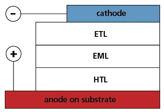
Electroluminescence of organic molecules has been a well known phenomenon for more than 50 years.1,2 However, it wasn’t until the late 1980’s that it became promising for practical use. Successful application of organic luminescence in light-emitting devices required device structures that overcame the problems associated with the high resistivity of organic materials, and achieved a well-balanced charge injection from the electrodes into organics. These two problems were solved by Tang and van Slyke3 with the thin-film heterostructure concept for the organic LEDs (OLEDs). Figure 1 shows a schematic of a double heterostructure OLED consisting of three organic layers sandwiched between the electrodes. The organic layers adjacent to the cathode and anode are the electron transport layer (ETL), and the hole transport layer (HTL), respectively.

Figure 1.Schematic of a double heterostructure OLED consisting of a hole transport layer (HTL), electron transport layer (ETL), emissive layer (EML), and the electrodes.
During OLED operation, holes and electrons injected from the opposite electrodes are transported to the emissive layer (EML) where they recombine to form excitons. Film thicknesses of 500 Å or less lower drive voltages to the 5–10 V level, and separate hole and electron conducting layers provide efficient charge injection and carrier recombination. This leads to exciton formation, and ultimately emission as the exciton decays to the ground state. Shortly after the introduction of thin-film, heterostructure-based OLEDs, it was demonstrated that two-component emissive layers with emitter molecules doped into an appropriate host matrix increase the device efficiency by improving the level of charge recombination and exciton confinement in the emissive layer. This also eliminates self quenching of the emitting dopants.4
Increasing Efficiency of OLEDs Using Phosphorescence
The hole and electron in OLEDs are odd electron species with an equal distribution of ms = ± ½. Thus, when the hole and electron recombine to form the exciton, a statistical mixture of singlet and triplet excitons are generated.5,6 This leads to a population of excitons that is 25% singlet and 75% triplet and has a profound effect on OLED efficiency. Most of the emitting dopants developed for OLEDs prior to the late 1990’s emit from fluorescent states, which only utilize the singlet fraction of formed excitons.7 This limits the internal quantum efficiency of fluorescence based devices to 25%, corresponding to an external efficiency (front face) of only about 5%. In the late 1990’s a new family of emissive dopants was introduced that gave marked increases in OLED efficiency. The key to this enhanced efficiency was the recognition that the triplet exciton fraction is more important than the singlet. Efficient harvesting of triplet excitons requires a phosphorescent dopant, which will trap both singlet and triplet excitons. An added requirement for the phosphorescent dopant is that it has a radiative lifetime comparable to the RC time constant of the OLED, which is typically in the microsecond time scale. The best way to achieve both high phosphorescence efficiency and a radiative lifetime on the order of microseconds is to incorporate a heavy metal atom into the dopant, whose spin orbit coupling will efficiently promote intersystem crossing between singlet and triplet states. The most commonly used metal for this purpose is Ir, however, efficient phosphorescent dopants have been also prepared with other heavy metals as well, including Pt, Ru, Re, Au and Os.
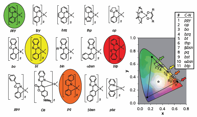
Figure 2 shows structures and the CIE color coordinates of a number of Ir-based organometallic dopants. OLEDs have been prepared with the four circled dopants; their CIE coordinates are labeled with colored arrows. Since the introduction of Ir based phosphors in OLEDs in 1999,8 close to 200 different Ir complexes have been incorporated into OLEDs, most giving external efficiencies of 8% or greater.9 Several groups have reported that use of Ir based materials in optimized devices can give external efficiencies > 20%, corresponding to internal efficiencies of close to 100%.10–12

Figure 2.Chemical structures, CIE (Commission Internationale de L’Eclairage) chromaticity coordinates of OLEDs, and phosphorescence spectra of iridium cyclometalated complexes. The CIE coordinates for OLEDs with the ppy2Ir(acac), bt2Ir(acac), pq2Ir(acac), and btp2Ir(acac) phosphorescent dopants (the circled structures on the left) are marked with colored arrows. The CIE coordinates of the phosphorescence spectra of the rest of the C^N2Ir(acac) complexes are also shown in square boxes on the CIE diagram. The NTSC standard coordinates for the red, green, and blue subpixels of a CRT are at the corners of the black triangle.
The emission energy for organometallic phosphors is closely related to the structure of organic ligands, making it possible to design a series of efficient phosphorescent emitters that covers most of the visible spectrum.13,14 The metal center of the complex can also be used to fine tune its emission energy. The emission from a transition metal complex originates from its lowest energy triplet excited state. Spectroscopic analysis shows that this state is predominantly localized on the cyclometalating ligands, mixed with singlet metal-toligand charge transfer (1MLCT) character. Modification of ancillary (“non-emissive”) ligands affects the energy of the metal orbitals and thus the amount of 1MLCT character in the excited state. Varying the ratio of ligand centered to 1MLCT character directly affects the energy of the mixed excited state.13 Thus, with modification of the ancillary ligand in (F2ppy)2Ir(L^X) complexes (L^X=ancillary ligand) it is possible to shift the emission energy of the complex from 458 to 512 nm. One of the deep blue complexes of this series [(F2ppy)2Ir(pz2Bpz2)] has been used to fabricate OLEDs which give external efficiencies > 11%.15
WOLEDs: Application of OLEDs in Illumination
An important potential application for LEDs is in illumination. The requirements for devices that serve as illumination sources are somewhat different than for the monochromatic OLEDs described above. OLEDs targeted for RGB displays have to give electroluminescent spectra with a relatively narrow lineshape centered on the peak wavelength. On the other hand, an illumination source is meant to approximate the blackbody solar spectrum and needs to have a broad lineshape with roughly equal intensity across the entire visible spectrum. Therefore, in order to attain complete coverage across the visible spectrum, an OLED used for illumination purposes typically employs multiple emitters that are either co-deposited into a single emissive layer or distributed into different layers or regions of the device. A number of the different device architectures have been reported to achieve efficient white electroluminescence.
Most white organic LEDs (WOLEDs) utilize luminescence from several different colored emitters such that the combined output covers the visible spectrum uniformly. While WOLEDs with less than three distinct emitters have been reported, the most common approach in WOLEDs is to use three, i.e. blue, green and red. One of the simplest device architectures involves mixing blue, green and red dopants into a single emissive layer, such that the sum of the three emission spectra covers the visible spectrum.16–18 The use of phosphorescent emitters in a triple doped emissive layer can then lead to highly efficient devices. However, using three dopants in a single layer is problematic because energy readily transfers from the higher energy blue dopant to the green dopant and from the green dopant to the red dopant. Therefore, careful adjustment of the concentration of each dopant is required to achieve a well-balanced emission color, with doping levels in the ratio blue > green >> red. In order to get well-balanced white emission, the doping level of the red dopant typically needs to be well below 1%.
One solution to the inter-dopant energy transfer problem is to segregate the dyes into different layers. Efficient WOLEDs have been prepared using this stacked concept with either fluorescent18–20 or phosphorescent emitters.21 More simplified structures have also been described that use dual component fluorescent blue and orange emitters doped into separate layers.19,22 While stacking the emitters in separate layers eliminates these energy transfer problems, the device architecture can become significantly more complicated due to difficulties in achieving balanced carrier recombination and exciton localization within each of the emitting layers.
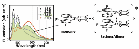
The use of planar platinum based dopants makes it possible to prepare a broadband emitting (white) OLED with only a single dopant, contrary to approaches described above, which utilized two or three different emitters. Figure 3 shows how the white color is achieved by combining the emission from the monomer (blue) and the aggregate (yellow-to-red) of the same organometallic platinum complex, giving an emission spectrum that covers the full range of visible wavelengths. The ratio of the monomer-to aggregate emission is controlled by both the doping concentration and the steric bulk of the dopant.23 Increasing the steric bulk on the dopant impedes the aggregate formation, whereas increasing the dopant concentration favors it. Minimizing the number of dopants significantly reduces the complexity of the device. It has recently been shown that devices based on the monomeraggregate approach to broadband emission can be used to achieve external efficiencies of 15–20%.24,25

Figure 3.Photoluminescence spectra of F2-ppyPt(acac) doped films showing the spectral lineshape dependence on the doping level. The spectra consist of aggregate and monomer emission components. At doping concentration of 5.6%, the F2-ppyPt(acac) monomer-to aggregate ratio in the film is balanced to produce white light. Chemical structures of F2-ppyPt(acac) and its dimer are shown on the right.
White light is composed of roughly 25% blue, with the balance covering the energies between green and red. It also happens that the excitons formed on recombination of the holes and electrons in the OLED are formed in a ratio of 25% singlets to 75% triplets. The similarity in blue fraction of white light and the singlet fraction suggests an alternative approach to achieving high efficiency white emission: couple the singlet excitons to a blue fluorescent dopant and the triplets to phosphors covering the green and red portions of the spectrum. Such an implementation of combined fluorescent and phosphorescent emission has proven to have a number of advantages. Introduction of the stable fluorescent blue is expected to alleviate a well-known problem of limited operational life times of blue components of WOLEDs. The shape of the quantum efficiency-current density plots of the phosphorescent three-component WOLED, typically shows a steep roll-off of the efficiency curve at higher current densities soon after the efficiency achieves its maximum.26 Triplet–triplet annihilation responsible for the unwanted efficiency decrease at high currents is decreased in the combined fluorescent/ phosphorescent device, since the triplets are at lower concentration in the middle of the emissive layer than near the ETL or HTL interface where they are formed.
A significant advance has recently been reported for phosphorescent based WOLEDs. Nakayama, et. al., have prepared a WOLED in which blue, green and red phosphors are used to generate a broad spectrum white OLED.27 Their device gave an efficiency of 64 lm/W at a brightness of 1000 cd/m2. This efficiency exceeds compact fluorescent sources and is close to that of fluorescent tube sources (ca. 75–90 lm/W). Moreover this device gave a device lifetime of greater than 10,000 hours at this brightness. These values are more than a factor of two higher than the previous records for OLEDs and clearly show that OLEDs have a bright future in lighting.
Conclusion
OLEDs have promise to make a marked impact in full-color displays and lighting applications. Both of these families of devices require high efficiency and long lifetime, as well as low-cost fabrication, a wide-gamut for sets of devices and high color saturation. OLEDs have demonstrated all of these properties; however, large area fabrication remains a significant challenge, making manufacturing costs quite high. Another technological challenge is the device lifetimes for deep blue devices. There are a large number of stable red and green phosphorescent emitters, giving device lifetimes approaching 106 hours. In contrast, the operational stability of the blue phosphor-based OLEDs are typically markedly shorter, with the best values between 15K and 20K hours. The source of the enhanced instability of these blue devices is still an open question. While many fluorescent and phosphorescent OLEDs have been commercialized in small area mobile displays, there is still ample room for scientific investigation to better understand the parameters controlling and limiting organic electroluminescence.
References
To continue reading please sign in or create an account.
Don't Have An Account?