Synthesis and Applications of Graphene Nanoribbons Synthesized
- Introduction
- Top-Down Synthesis of GNRs from Unzipping of Nanotubes
- Application of GNRs for Neurophysiological Recovery
- Applications of GNRs in Batteries
- Applications of GNRs for De Icing
- Conclusion
Introduction
Graphene nanoribbons (GNRs) are quasi one-dimensional narrow strips of graphene comprised of sp2-hybridized carbon atoms arranged into hexagonal honeycomb lattice configurations. The high aspect ratio, abundant edges, conductivity, and propensity for functionalization make GNRs an attractive material that draws interest from a wide range of fields, including chemistry, physics, materials science, and biology. GNRs have already found use in various applications such as sensors, conductive films, polymer composites, batteries, energy-conversion/storage devices, bioimaging, DNA sequencing, and neurophysiological recovery. Here, we will review the prevalent top-down synthetic methods to GNRs, as well as the current applications for these materials.
Top-Down synthesis of GNRs from unzipping of nanotubes
Bottom-up and top-down methods are both currently used for the synthesis of GNRs. Bottom-up approaches allow for the synthesis of precise narrow ribbons due to the controllable assembly of small molecule building blocks.1-2 Although this method results in high-quality GNRs with minimal defects, the scalability of GNR synthesis via this route is less feasible; therefore, top-down methods are preferred when lower-cost mass-production is desired. Such top-down approaches often involve the longitudinal unzipping of multi-walled carbon nanotubes (MWCNTs) to produce GNRs that are as long as the starting MWCNTs had been. Redox chemistry is commonly used for such longitudinal splitting of MWCNTs with many publications reporting successful GNR fabrication under both reductive and oxidative conditions. The former typically employs the use of potassium (K) vapor or sodium-potassium alloy (Na/K) reducing agents whereas the latter uses oxidizing agents, such as potassium permanganate (KMnO4) or ammonium persulfate (NH4)2S2O8.3-8 Each method of GNR synthesis necessitates the use of low-defect MWCNTs since defects act as termination sites that prevent completion of the unzipping reaction.
Both the reductive splitting of MWCNTs by K vapor and the solution-based Na/K methods were developed by the Tour group.3-4 In the former, MWCNTs are exposed to K in the vapor phase by heating the two together in a sealed glass tube to 250 °C for 14 h;3 however, the solution-based approach has greater utility. In that, GNRs are obtained by suspending MWCNTs in 1,2-dimethoxyethane (DME) (259527) followed by the addition of Na/K alloy (2:9 molar ratio). The reaction mixture is allowed to stir at room temperature for 3 d before the product and excess reagents are quenched and purified. All synthetic steps are performed under inert atmosphere.4 In this process, K atoms intercalate within the interstices of the concentric MWCNT walls, resulting in blistering around the metal atoms and longitudinal cracking of the walls. The presumed aryl radicals receive another electron from the metal to form the aryl anions. Since the carbon atoms found along the edges at which the cleft in the sidewall is formed are in the reduced carbanionic state, the edge carbon atoms are highly reactive and are prone to electrophilic attack. The carbanions can either be quenched via the addition of MeOH to produce protonated (H-terminated) GNRs or functionalized with varying moieties, depending on the targeted properties of the material (Figure 1). For example, edge functionalization of the GNRs with alkyl or poly(ethylene glycol) (PEG) moieties has shown to significantly improve the dispersibility of GNRs in organic or aqueous solvents, respectively, while leaving the basal planes intact. By preserving the sp2-hybridized basal plane, the conductivity of the GNRs is retained while altering the chemical properties at the edges through functionalization, allowing for increased dispersibility and interfacial interactions of the functionalized GNRs with other materials. Such interactions are advantageous for the production of composites. For instance, conductive fillers can leverage the high aspect ratio and conductivity of the functionalized GNRs to achieve smaller mass loadings while still providing percolation. It should be noted that although GNRs synthesized via reductive-intercalation assisted unzipping are highly conductive, the strong van der Waals forces between the GNR stacks present a challenge for effectively exfoliating the material into monolayer ribbons.
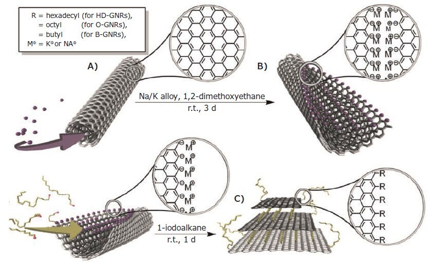
Figure 1. Reductive intercalation-driven synthesis of alkyl functionalized GNRs. A) The MWCNT is split by the intercalation of K between the walls of the nanotube due to strain along the carbon-carbon bonds induced by the metal atoms. B) Carbanions are formed along the nanoribbon edge after splitting of the MWCNT walls. C) Functionalization of the GNRs with alkyl moieties: the same process is used for the synthesis of H-terminated GNRs or PEGGNRs, but MeOH or ethylene oxide are added during the second step, respectively, instead of 1-iodoalkane.4
In 2009, the Tour group established a method for oxidatively splitting MWCNTs to form GNRs reminiscent of synthesizing graphene oxide (GO) from graphite by the Hummer’s method. This top-down method consists of dispersing in concentrated H2SO4 followed by the addition of KMnO4. The reaction mixture is stirred at room temperature for 1 h and then heated at 55–70 °C for 1 h.5 Once purified, the resulting product is highly soluble in a wide range of solvents including water, ethanol, and various polar organic solvents. Unlike GNRs synthesized by reductive splitting, oxidatively produced GNRs are readily exfoliated due to the carboxylate anionic charges, allowing for single-layer ribbons to be acquired. However, this ease of exfoliation comes at the expense of reduced conductivity of the GNR product since the sp2-hybridization of the basal plane is lost due to defects induced by the oxidation reaction. Initially, this process was thought to be driven by oxidative chemical-bond cleavage.5 This mechanism has since been revised to one proposing intercalation-driven unzipping similar to the reductive splitting method. Three consecutive steps occur: (1) intercalation-unzipping of the MWCNT precursor, (2) oxidation of the nanoribbons, and (3) exfoliation of the multilayer GNR stacks (Figure 2).6 Molecules of H2SO4 intercalate between the walls of the MWCNT via entrance through the opened ends of the nanotubes or through vacancy defects that are already present in the walls. The intercalated H2SO4 causes outward radial expansion of the nanotube that induces unzipping to the foliated GNR product. Following successful unzipping of the nanotubes, oxidation of the edges and basal plane of the GNRs can occur. The oxidized GNR stacks can then be exfoliated upon exposure to water. By altering the ratio of KMnO4/MWCNT (by weight) or the reaction duration, it was determined that the oxidative splitting reaction can be terminated at any of the aforementioned steps. Therefore, the reaction conditions can be controlled to produce GNRs with varying properties, ranging from non-oxidized multilayered GNR products with uncompromised conductivity to heavily oxidized single-layer GNRs with facile dispersion in water but lower conductivity. To produce GNRs by oxidative splitting without sacrificing conductivity, milder oxidants can be used instead of KMnO4. For instance, (NH4)2S2O8 (215589) has shown to be effective at unzipping MWCNTs without introducing a significant number of oxygen defects along the graphene basal plane. This unzipping protocol calls for the suspension of MWCNTs in a mixture of oleum (435597) and concentrated H2SO4 (339741) (1:1 ratio by volume) before adding (NH4)2S2O8 and heating under reflux at 80 °C for 1 d.7-8
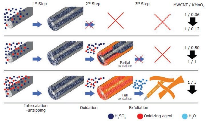
Figure 2. Mechanism of unzipping MWCNTs by oxidizing agents. The oxidative splitting of MWCNTs occurs in three consecutive steps: intercalationunzipping, oxidation, and exfoliation. Since each step occurs sequentially, the reaction can be terminated at any step by controlling the reaction conditions (ratio by weight of MWCNT/KMnO4). GNRs ranging from non-oxidized (gray color of MWCNT wall) to heavily oxidized (red color of MWCNT wall) can be produced, allowing desired properties of the nanoribbons to be targeted (i.e. conductivity or effective dispersibility in water or organic solvents).6
Application of GNRs for neurophysiological recovery
We have conducted a study which shows that nontoxic poly(ethylene glycol) graphene nanoribbons (PEG-GNRs) generate a permissive microenvironment for spinal cord recovery after injury (Figure 3).9 GNRs are functionalized with PEG via reductive splitting of MWCNTs followed by subsequent anionic polymerization with ethylene oxide, rendering a product with water-soluble PEG moieties that emanate from the edges of the GNR. The edge functionalization of the GNRs maintains the pristine basal planes and, therefore, the electrical conductivity of the carbon core. Since these basal planes are highly electrically conductive, neuronal growth can be stimulated along the graphene-based material.9-12 The primary structural components of PEG-GNRs provide a permissive microenvironment conducive for spinal cord recovery; the composite material spans the gap between severed axons, forming a nanoscaffold capable of facilitating the conduction of neuronal signals across the lesion while permitting growth along the framework.9, 13-14 Thus far, we have shown in 5 rats that the application of 0.5 mL of 1% PEG-GNRs solution in PEG600 (807486) at C5 after complete cervical transection resulted in ~30% restoration, of the pre-surgery somatosensory evoked potential (SSEP) amplitude within 24 h. One animal with no SSEP measurements regained mobility of its forelimbs and hindlimbs within two weeks after surgery, and scored 19 out of 21 by week three on the Basso, Beattie, and Bresnahan (BBB) motility scale (Figure 3).14 This can be seen in an online video.15

Figure 3. A)Mobility recovery of a single rat following intra-topical application of 1% PEG-GNRs in PEG600 to blunt ends of transected spinal cord compared to PEG600 alone and PBS alone. Dashed lines guide the eye. B) Yellow bar represents the spinal cord, red represents cut or injured area, and black represents area where PEG-GNRs have been applied. C) Postulated mechanism of repair: PEG-GNRs provide a microenvironment where growth is encouraged, and the conductive nature of the graphene allows neurons to communicate with each other over a distance and grow towards each other along the nanoribbon scaffold.
Applications of GNRs in batteries
The high aspect ratio of GNRs enables them to provide percolation at a lower mass loading than other carbon species such as carbon black, graphene nanoplatelets, and graphite. This property has made GNRs a good candidate for a conductive filler in batteries. Over the past decade, many papers using GNRs in batteries have been published.16-18
We have used GNRs, polyacrylonitrile, and sulfur to make a sulfurized carbon (SC) cathode to pair with Li-metal anodes (Figure 4).16 The full battery (FB) based on the graphenecarbon nanotube-Li (GCNT-Li)/SC cathode is demonstrated with high energy density (752 Wh kg-1 total electrodes, where total electrodes = GCNT-Li + SC + binder), high areal capacity
(2 mAh cm-2), and cyclability (80% retention at >500 cycles) and is free of Li polysulfides and dendrites that would cause severe capacity fade.
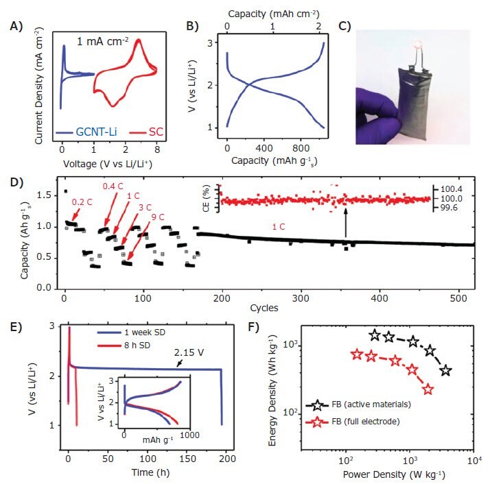
Figure 4.Measurements in a full battery with a GCNT-Li anode and SC cathode. A) CVs of GCNT-Li and SC cathode half-cells in 4 M LiFSI/DME at 0.5 mV s-1. B) Galvanostatic charge/discharge curves of the FB at 0.1 C with areal capacity of 2 mAh cm-2. C) Photograph of a FB prototype powering a LED. D) Sequential rate performance test (0.2 to 9 C) and cycling stability of the FB. Inset: CE (%) of the rate and stability test. The reference blue dashed line is set to 99.9%. E) Self-discharge (SD) tests of the FB after 8 h and 1 week showing charge curve followed by continuous discharge curve during and after the open circuit period. Inset: Voltage vs capacity of the SD tests. F) Ragone plot of the GCNT-Li/SC FB, here considering the combined mass of the anode and cathode active materials (Li and S) and the full electrode mass (including binder, carbon additives, GCNT, excess of Li), excluding the current collector.16
We have also developed a composite material from graphene nanoribbons and iron oxide nanoparticles that provides a remarkable route to lithium-ion battery anodes with high specific capacity and cycle stability.17 At a rate of 100 mA/g, the material exhibits a high discharge capacity of ~910 mAh/g after 134 cycles, which is >90% of the theoretical Li-ion storage capacity of iron oxide (Figure 5). Utilizing graphene nanoribbons as a conductive platform on which iron oxide nanoparticles are formed combines the advantages of long carbon nanotubes and flat graphene surfaces (Figure 5). The high capacity over prolonged cycling achieved is due to the synergy between electrically percolating networks of conductive graphene nanoribbons and the high lithium-ion storage capability of iron oxide nanoparticles.
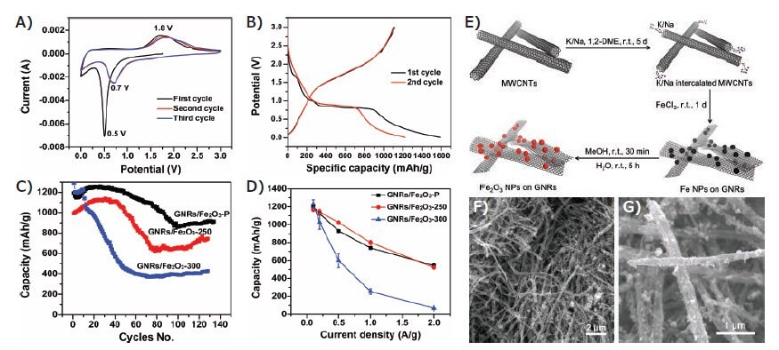
Figure 5.Electrochemical properties of GNR/Fe2O3 composite anode electrodes. All of the capacities shown here are based on the weight of iron oxide NPs. A) Cyclic voltammetry of the GNR/Fe2O3-P composite anode. B) The first and second charge-discharge curves of the composite GNR/Fe2O3-P anode. C) Comparison of the cyclability of GNR/Fe2O3-P, GNR/Fe2O3-250, and GNR/Fe2O3-300 at a rate of 0.2 A/g. D) Comparison of rate performance of GNR/Fe2O3-P, GNR/Fe2O3-250, and GNR/Fe2O3-300. E) Scheme of the synthesis of the GNR/Fe2O3 composites. F) Low magnification scanning electronic microscope (SEM) image of the GNR/Fe2O3-P composites. G) High magnification SEM image of the GNR/Fe2O3-P composites.17
Apart from conventional Li-ion battery anodes, we have designed an asphalt-derived (Asp) porous carbon-graphene nanoribbon (Asp-GNR) composite material as a substrate for Li plating in Li metal anodes.18 GNRs were added to enhance the conductivity of the host material at high current densities to produce Asp-GNR-Li. Asp-GNR-Li has demonstrated remarkable rate performance from 5 A/g Li (1.3C) to 40 A/g Li (10.4C) with Coulombic efficiencies of >96% (Figure 5). Stable cycling was achieved for more than 500 cycles at 5 A/g Li, and the areal capacity reached up to 9.4 mAh/cm2 at a maximum discharging/ charging rate of 20 mA/cm2 that was 10× faster than that of typical LIBs, suggesting utility in ultrafast charging systems.
Applications of GNRs for Deicing
High conductivity also makes GNRs a promising material for deicing and anti-icing devices. Owing to the carbon anions generated during the reductive splitting process, GNRs can be easily functionalized on the edge to become superhydrophobic. In a previous work, we have designed a perfluorododecylated graphene nanoribbon (FDO-GNR) film that takes advantage of both the low polarizability of perfluorinated carbons and the intrinsic conductive nature of graphene nanoribbons (Figure 6).19 The FDO-GNR films are superhydrophobic with a sheet resistance below 8 kΩ/sq and exhibit an anti-icing property that prevents freezing of incoming ice-cold water down to -14 °C. At lower temperatures, voltage can be applied to the films to resistively heat and deice the surface. A spray-coating method makes this method suitable for large-scale applications. The anti-icing and deicing properties render the FDO-GNR films promising for use in extreme environments.
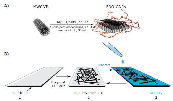
Figure 6. A) Schematic illustration of the synthesis of FDO-GNRs and B) fabrication of FDO-GNR films.19
In another work, we demonstrated a GNR-epoxy composite for deicing the surface of rotor blades.20 A conductive composite of GNR stacks and epoxy was prepared. The epoxy is filled with the GNR stacks, which serve as a conductive additive. The GNR stacks are, on average, 30 nm thick, 250 nm wide, and 30 μm long. This GNR-filled epoxy composite exhibits a conductivity of >100 S/m at 5 wt% GNR content, which permits application of the GNR-epoxy composite for deicing of surfaces through Joule (voltage-induced) heating generated by the voltage across the composite. A power density of 0.5 W/cm2 was delivered to remove ~1 cm-thick (14 g) monolith of ice from a static helicopter rotor blade surface in a -20 °C environment.
Conclusion
The cost-effective and facile production of GNRs synthesized by either reductive or oxidative unzipping of nanotubes makes high production rates more feasible. This increases the practicality of utilizing these GNRs in numerous applications, primarily ones associated with lithium-ion batteries, conductive thin films, and polymer composites; however, even more promising would be the mass production of a conductive nanoscaffold therapeutic device for the restoration of mobility after spinal cord injury. Owing to the unique and facile tunability of the GNR properties, the potential breadth and depth of applicability for these quasi, one-dimensional graphene structures are exceedingly broad and capable of crossing a multitude of fields.
Materials
References
To continue reading please sign in or create an account.
Don't Have An Account?