Commercial Quantum Dots: Synthesis & Apps
Introduction
Quantum dots (QDs) are luminescent semiconductor nanoparticles, with diameters in the range of 1 to 20 nm. The unique optical and electronic properties of QDs are being exploited in a number of applications including flat panel displays and coloured lighting along with fluorescent imaging in biological and medical diagnostics. It is envisaged that QDs may replace many of the existing organic dyes and inorganic phosphors currently used in imaging, display and lighting devices.
Quantum confinement of electrons in semiconductor crystals with well-defined 3-dimensional nanoscale size is the origin of unique QD properties compared to conventional materials.1-4 Fundamentally, the quantum confinement effect results in an increasing semiconductor bandgap with decreasing QD size. This allows size-dependent tuning of the semiconductor photoluminescence emission wavelength throughout the visible spectrum. Combined with a very sharp emission spectrum and high quantum efficiency, it makes QDs ideal luminophors for many optoelectronics and imaging applications. Just as the synthesis of high quality macroscale semiconductors has facilitated the development of optoelectronics over 5 decades ago, nanoscale control of semiconductor architecture to make QD nanoparticles can enable future technologies, including high-efficiency solar cells, solid-state light sources, and ultra-bright displays.
Nanocrystals are often described as “artificial atoms.” Like atoms, electron energy levels of nanocrystals are discrete but the fundamental difference is that the level spacing and other quantum mechanical properties can be tailored by adjusting the nanocrystal size. If we consider a nanocrystal like an artificial atom, then it should be possible to combine them into “nanocrystal molecules” and “nanocrystal solids” or, more generally, into nanocrystal assemblies in the same way as observed with real atoms. Therefore QD nanocrystals can be considered as building blocks of new solid-state materials and devices with novel physical properties. Building upon the development of synthetic routes to high quality QDs and a rigorous understanding of the physical properties of individual QDs, it is possible to control and manipulate QD assemblies and open up routes to fabrication of novel devices with enhanced physical, optical and electronic properties.
High-quality QDs: Shelling and Organic Passivation
Quantum confinement effects exist in many nm-scale semiconductor structures. However, simply reducing size of semiconductor colloids down to nm-scale is insufficient for making high-quality QDs for demanding commercial applications. Important metrics for describing QDs useful in applications are: 1) fluorescence quantum yield (QY), defined as the ratio of the number of photons emitted to the number of photons absorbed reported as a percentage; 2) narrow particle size distribution below +/- 5%; 3) sharp emission peak widths defined by their full width half max (FWHM), that is, the width of the peak half way up the emission spectrum.
QDs have surface atoms with available coordination sites that render them highly reactive and susceptible to particle agglomeration. To overcome this problem QDs are passivated by capping the surface atoms with protecting groups. Capping the QDs serves four purposes: 1) it prevents particle agglomeration, 2) protects the particle from the surrounding chemical environment, 3) provides additional electronic stabilization to the surface, and 4) controls solubility in a specific solvent system. The capping agent usually takes the form of a Lewis base covalently bound to surface metal atoms. Other capping agents such as an organic polymer forming a sheath around the particle have also been employed to enhance particle stability.
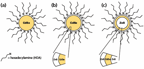
Simple semiconductor colloids consisting of a crystalline core and an outer organic passivating layer can have relatively low QY due to electron-hole recombination occurring at defects and dangling bonds situated on the nanocrystal surface. Building up complex 3-dimensional nanocrystal architectures can substantially enhance size-dependent luminescence of core semiconductor nanoparticles. Growing a second, wider bandgap inorganic material over the core will eliminate core surface defects and dangling bonds. The resulting core/shell QDs have greatly improved QY. An alternative strategy employed by Nanoco is to prepare a core/multi-shell structure where the electron-hole pair is completely confined to a single shell layer.5 This is known as a quantum dot-quantum well (QDQW) structure, and consists of a wide bandgap core, followed by a thin layer (1–5 monolayers) of a narrower bandgap material which is then surrounded by another wide bandgap material, e.g. ZnS/CdSe/ZnS. These QDQWs exhibit clear confinement of photo-excited carriers in the CdSe layer and the emission wavelength can be tuned by changing the thickness of the CdSe shell. The QDQW methodology is especially useful for making high quality blue-emitting QDs with improved optical and chemical stability. Schematics of core, core/shell and core/multi-shell QDs are described in Figure 1. By making reproducible core-shell and core/multishell nanocrystals, Nanoco is able to provide QDs with exceptional stability and very high QY, required in a variety of technological applications.5

Figure 1. 3D architectures of QDs: (a) A core particle consisting of a CdSe core and HDA organic capping agent. (b) A core-shell particle consisting of a CdSe core, a ZnS shell, and HDA capping agent. (c) A core-multi shell (QDQW) particle consisting of a ZnS core and a CdSe shell followed by a ZnS shell with HDA capping agent.
Enabling applications — Scaling up QD production
To make QDs useful for lighting and display applications, synthetic routes are needed to reproducibly yield pure, high-quality, monodispersed crystalline QDs. These synthetic methods must be scalable. For example, for use as a down conversion phosphor, milligram quantities are needed per LED but, because millions of LEDs are fabricated monthly, synthetic methods capable of delivering multi-kilogram quantities are required. To do this, Nanoco developed “molecular seeding” methods.6-8
Until recently, the main method employed to prepare semiconductor QDs was classical colloid chemistry of controlled or arrested nanocrystal precipitation from precursor solutions. Typically, separate elemental precursors needed to form a compound semiconductor were rapidly injected into a reaction flask to achieve rapid homogeneous nucleation of semiconductor nanocrystals. These “dual injection” methods work well for smallscale synthesis where one solution can be added rapidly to another while maintaining a constant temperature throughout the reaction. With increasing reaction scales rapid injection of large solution volumes into one another results in temperature differentials and culminates in wide particle size distributions. Nanoco Technologies’ molecular seeding methodology has been developed to enable reproducible routes to larger quantities of crystalline, narrow size-dispersity, stable QDs. In the presence of a molecular cluster compound and chemical precursors, QDs are produced under conditions whereby the integrity of the molecular cluster is maintained and acts as a prefabricated seed template. A schematic of the molecular seeding methodology is described in Figure 2. Individual molecules of a cluster compound act as seeds or nucleation points upon which nanoparticle growth can be initiated. Consequently, because suitable nucleation sites are already provided in the system by the molecular clusters, a high temperature nucleation step is not necessary to initiate nanoparticle growth and the methodology is scalable. Nanoco has demonstrated that each individual molecular cluster does indeed end up as a QD.9
![Molecular seeding synthesis of a cadmium selenide quantum Molecular seeding synthesis of a cadmium selenide quantum dot using [M10Se4(SPh)16][x]4 x = Li+ or (CH3)3NH+ as the molecular seed and dropwise addition of cadmium acetate (Cd(OAc)2) and tri-n-octylphosphine selenide (TOPSe) as the cadmium and selenium element-source precursors, with hexadecylamine (HDA) used as the capping agent.](/deepweb/assets/sigmaaldrich/marketing/global/images/technical-documents/articles/materials-science-and-engineering/nanoparticle-and-microparticle-synthesis/molecular-seeding-synthesis-of-a-cadmium-selenide-quantum-dot.fig2.gif)
Figure 2.Figure 2 Molecular seeding synthesis of a cadmium selenide quantum dot using [M10Se4(SPh)16][x]4 x = Li+ or (CH3)3NH+ as the molecular seed and dropwise addition of cadmium acetate (Cd(OAc)2) and tri-n-octylphosphine selenide (TOPSe) as the cadmium and selenium element-source precursors, with hexadecylamine (HDA) used as the capping agent.
Future: CFQDs-Cadmium Free Quantum Dots
The use of cadmium and other restricted heavy metals in semiconductor QDs is a major concern for commercial applications. In many regions of the world there is now, or soon will be, legislation to restrict and, in some cases, ban the use of materials containing heavy metals including Cd, Hg, and Pb.10 Nanoco’s molecular seeding method has been adapted for other compound semiconductor materials (e.g. III-V’s), which have similar optical properties to those of CdSe QDs, but do not contain heavy metals. Over the coming months, Nanoco plans to provide small samples of these materials for commercial sale through Sigma-Aldrich®.
Case Study Quantum Dot Solid State Lighting (QD-SSL)
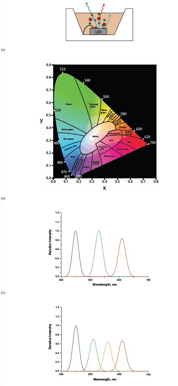
The white light LED market is hugely important, with the promise of increased lamp lifetimes and efficiencies paving the way for a revolution in the lighting industry. Color rendering and efficiency are the two most important criteria for traditional light sources for general lighting. Lamp color is typically specified according to the CIE 1931 chromaticity diagram (Figure 3). The ability of a light source to illuminate an object’s true color is denoted by its color rendering index. For example, sodium lamp street lighting has poor color rendering capability as it’s difficult to distinguish a red car from a yellow car.

Figure 3. Schematic of quantum dot LED: QDs are optically pumped by a visible blue GaN LED to produce green and red photoluminescence. The mixture of red, green and blue produces a white light. (b) CIE 1931 chromaticity diagram: A mixture of two colors produces a new color whose xy coordinate falls on the line connecting their respective xy coordinates. A mixture of three colors produces new color whose xy coordinate falls within a triangle whose vertices correspond to the xy coordinates of the three independent colors. The location of the coordinates of the mixed color will depend on the relative intensities of the source colors. (c) Spectrum of a trichromatic-dual QD LED utilizing blue LED chip with green and red QDs. (d) Spectrum of a quadchromatic-triple QD LED blue LED chip; green, yellow and red QDs. Note: both spectra have 1931 CIE x,y coordinates of 0.311, 0.324 but the color rendering index increases from c to d.
Current white light LED technology utilizes a cerium doped YAG:Ce (yttrium aluminium garnet) down-conversion phosphor pumped by a blue (450 nm) LED chip. The combination of blue light from the LED and a broad yellow emission from the YAG phosphor results in white light. Unfortunately, this white light often appears somewhat blue and is often described as “cold” or “cool” white. QDs can be used as LED down-conversion phosphors because they exhibit a broad excitation spectrum and high quantum efficiencies. Furthermore, the wavelength of the emission can be tuned completely across the visible region simply by varying the size of the dot or the type of semiconductor material. As such, they have the potential to be used to generate virtually any color and, more importantly, warm whites strongly desired by the lighting industry. Additionally, by using a combination of one to three different types of dots with emission wavelengths corresponding to green, yellow, and red it is possible to achieve white lights of different color rendering indexes (Figure 3). Because of these attractive features, QD-LEDs are beginning to receive attention from both industrial and academic researchers.11-15
In addition to white lighting for general illumination, there are other opportunities for QD-LEDs. For example, green LEDs are not particularly efficient, thus green-emitting QDs on top of an efficient blue LED chip may be a solution. Similarly, amber LEDs suffer from temperature dependencies and thus a QD solution may be applicable. Furthermore, because of the widely tunable QD emission, it’s possible to have near UV-pumped QD-LEDs with combinations of QDs which emit virtually any color on the chromaticity diagram. This could have important applications in signage by, for example, replacing neon bulbs.
References
To continue reading please sign in or create an account.
Don't Have An Account?