Streamlined Electrode Fabrication: A User-Friendly Guide
Abstract
As the demand for efficient energy storage solutions continues to rise, optimizing electrode materials and fabrication methods has become increasingly critical. This guide provides a comprehensive framework for the fabrication of cathode electrodes utilizing lithium nickel manganese cobalt oxide (NMC811), a prominent material recognized for its high energy density and stability. It outlines standardized procedures for material preparation, slurry formulation, coating, and post-processing, with a focus on achieving optimal performance in lab-scale battery production. By offering detailed standard operating procedures (SOPs), this guide supports the production of high-quality electrodes, deepens understanding of battery technology, and serves as a practical reference for experimental design in energy storage research and development.
Introduction
Lithium-ion batteries have emerged as the most widely adopted energy storage technology across a range of commercial applications, including electric vehicles (EVs), energy storage systems (ESS), and portable electronics. Their high energy density, long cycle life, and stable operating characteristics make them superior to alternative battery technologies, and they play a critical role in enabling more sustainable energy systems and reducing global carbon emissions.1 These technological advancements are largely driven by continuous innovations in battery materials and manufacturing processes, with electrode materials serving as a key factor in determining overall battery performance.
Among the various components, cathode materials are particularly critical, as they directly influence a battery’s capacity, voltage, cycle life, and safety. Two major classes of cathode materials dominate the current lithium-ion battery market: layered oxide materials, such as NMC (Nickel-Manganese-Cobalt oxides), and olivine-type materials, such as lithium iron phosphate, known as LFP.2 In particular, NMC811, a nickel-rich variant, has gained attention for its ability to deliver high energy density and power performance, making it a leading candidate for high-capacity EV batteries.
In addition to the intrinsic properties of electrode materials, the performance of lithium-ion batteries is strongly influenced by the manufacturing process, which dictates how these materials are integrated into practical electrodes. Laboratory-scale fabrication of 2032 coin cells generally follows a standardized sequence of steps, outlined in Figure 1: slurry preparation, slurry coating onto a current collector, drying under controlled conditions, calendaring to adjust electrode density and thickness, electrode punching, and final cell assembly.3 Each of these steps critically affects electrode porosity, adhesion, and electrolyte infiltration, thereby determining the electrochemical behavior of the cell.
The steps of laboratory-scale electrode fabrication are well outlined in the literature, but we see that a clear, step-by-step protocol that connects processing parameters to electrode characteristics could support researchers in designing and optimizing experiments. Therefore, this guide presents a standardized and practical approach to laboratory-scale electrode fabrication, using our NMC811 as an example. We provide a step-by-step protocol and troubleshooting to overcome common pitfalls.

Figure 1.Schematic illustration of the laboratory-scale electrode fabrication and 2032 coin cell assembly process. The workflow includes slurry preparation, coating onto an aluminum current collector, drying, calendaring, electrode punching, and final cell assembly. Each step plays a critical role in defining electrode microstructure, density, and adhesion, which ultimately determine electrochemical performance.
Experimental
This section describes the materials, instruments, devices, and accessories used in the methods
Materials and Instruments
All chemicals used in this study were used as received without further purification. The cathode active material, LiNi0.8Mn0.1Co0.1O2 (aka NMC811), the conductive additive Super P® (carbon black), and the solvent N-methyl-2-pyrrolidone (NMP, anhydrous, 99.5%) were obtained from Merck KGaA, Darmstadt, Germany. The binder, polyvinylidene fluoride (PVDF), was sourced from Arkema (Kynar® HSV 900). The electrolyte used was 1.0 M LiPF₆ in ethylene carbonate (EC) / dimethyl carbonate (DMC) / diethyl carbonate (DEC) = 1:1:1 (v/v/v), obtained from Merck KGaA, Darmstadt, Germany. Trilayer separators (PP-PE-PP, Celgard® 2320) and 2032-coin cell components were sourced from Wellcos. All procedures were conducted in a standard laboratory environment. However, steps involving moisture-sensitive materials were performed in an argon-filled glovebox (H₂O/O₂ < 0.1 ppm) to minimize exposure to ambient air.
Before starting the experiments, it is essential to familiarize yourself with the Safety Data Sheets (SDS) for all chemicals involved. Appropriate personal protective equipment (PPE) should be worn, and experiments should be conducted in a suitable safety environment, such as a fume hood.
Instrument(s) and Devices
- Glovebox compatible dual-shaft planetary vacuum mixer
- Compact tape casting coater w/ vac. chuck (200Wx365L mm) and film applicator and bottom heater
- NRTL certified 53L 200C vacuum oven (16x14x15") with digital temperature controller
- 110°C Hot rolling press
- Hand operated punching tool (diameter: 14 mm, 16mm, 19mm)
- Automatic coin cell crimper
Instrument Accessories
- 2032 coin cell parts
Other Reagents and Accessories
- BRAND® Transferpette® S pipette (BR705874, BR705880, and BR705882)
- Straight-Tip PVDF Tweezer with carbon tip (931187)
Laboratory-Scale Electrode Fabrication Method
This section describes methods for the preparation of the cathode slurry, coating process, post-coating treatment, cutting, and battery assembly.
Preparation of the Cathode Slurry
Drying: Water is often deleterious to electrochemical performance and can be inadvertently introduced into the cell by using materials with adsorbed moisture. To remove any residual moisture that may remain, it is helpful to pre-dry reagents, including carbon additives and cathode materials, in a vacuum oven at around 60°C prior to starting the experiment. This ensures optimal performance and prevents issues related to moisture content that can affect the electrochemical properties of the electrodes.
Weighing: For the preparation of the slurry, a total weight of 20 g is utilized to ensure adequate volume for mixing in a vacuum mixer. The components are weighed at a ratio of 90:5:5, where NMC811 constitutes 90% of the total weight, while Super P® and poly(vinylidene fluoride) (PVDF) each make up 5%.
Mixing: Begin by combining PVDF with 37.5 mL of 1-Methyl-2-pyrrolidone (NMP) solution in the vacuum mixer. This initial step is crucial for achieving a uniform binder solution. After thoroughly mixing the PVDF and NMP, gradually add the pre-weighed NMC811 and Super P® to the binder solution. We established a target solid content of approximately 35 wt% for the NMC811 and Super P®, which serves as the basis for determining viscosity. While there may be slight variations depending on the materials used, the goal is to achieve a slurry that is uniformly mixed without agglomerates and that is not too thin, ensuring it does not flow excessively on the current collector.4-7
Continue mixing the slurry in the vacuum mixer at a speed of 600 rpm for 20 minutes for the PVDF and NMP, followed by an additional 30 minutes after adding the NMC811 and Super P®. This process ensures a homogeneous slurry with a viscosity suitable for coating, free of lumps and inconsistencies. As illustrated in Figure 2, slurry viscosity strongly depends on the solid content: at 65 wt% the slurry is very thick and paste-like, while at 20 wt% it becomes overly fluid and spreads uncontrollably. We targeted an intermediate solid content of around 35 wt%, which resulted in a slurry that maintained good flowability without being too thin, allowing for uniform coating on the current collector. Figure 2 demonstrates this contrast through dripping tests, providing users with a visual reference to judge whether their slurry is within an appropriate viscosity range.

Figure 2.Viscosity-dependent dripping behavior of NMC811 cathode slurries with varying solid content. Representative photographs capture the moment when slurries with solid contents of 65, 55, 45, 35, 30, 25, and 20 wt% were dispensed using a spoon. Higher solid content slurries (65–55 wt%) exhibit high viscosity, remaining largely adhered to the spoon, whereas lower solid content slurries (25–20 wt%) flow rapidly and form elongated droplets. The 35 wt% slurry, positioned centrally, demonstrates an intermediate viscosity, forming well-defined droplets that detach from the spoon in a controlled manner, indicating an optimal consistency for uniform cathode coating. This visual comparison provides a practical guideline for selecting appropriate slurry solid content to achieve reproducible electrode fabrication.
Coating the Current Collector
Coating: Cut the aluminum foil to the desired dimensions, ensuring it is clean and free from contaminants. This step is critical, as any impurities can adversely affect the performance of the electrodes.8,9
The slurry was cast onto aluminum foil using a compact tape casting coater with a doctor blade. The initial wet coating thickness was set to approximately 140 µm, targeting an areal capacity of 1.8-2 mAh/cm². This thickness should be determined based on the intended capacity and application requirements, ensuring optimal performance of the electrode. After coating, the appearance of the electrode can be checked, as shown in Figure 3.1, where the 35 wt% slurry provides uniform coverage and appropriate areal loading.
Drying: Place the coated aluminum foil in a vacuum oven set to 80°C for a duration of 12 hours. This step facilitates the evaporation of the solvent (NMP), ensuring that the electrode is ready for subsequent processing. Maintain a vacuum pressure of 100 mTorr or lower during the drying process. Ensure proper ventilation in the drying area to avoid inhalation of any fumes.
Post-Coating Treatment
Electrode Calendering: After drying the electrodes, set the hot roll press to 100°C and adjust it to achieve a target thickness of 30 μm, including the thickness of aluminum current collector. This step is crucial for achieving a porosity of 38-43%, which ensures the production of uniform and dense electrodes.
The hot roll pressing process enhances the structural integrity of the electrodes, facilitating better electrochemical performance. Figure 3.2 shows the smooth and compact surface of the electrode after drying and calendering, confirming that the slurry viscosity and mixing conditions were suitable for reliable electrode preparation.
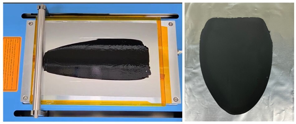
Figures 3.1 and 3.2. Electrode fabrication images:
3.1 Cathode coated using the optimized 35 wt% slurry, demonstrating appropriate areal loading and a uniform, defect-free layer with complete coverage.
3.2 Same electrode after drying and calendaring, showing a smooth and compact surface morphology, confirming ideal viscosity and mixing conditions for reliable electrode preparation.
Cutting: Once the rolling process is complete, use a hand-operated punching tool with a diameter of 14 mm to cut the cathode electrodes into the desired shape. Separately, cut the lithium metal anodes to 16 mm and the separators to 19 mm using appropriately sized punches. The cathode, anode, and separator are cut into different sizes to ensure proper cell stacking alignment and to prevent short-circuiting; slightly larger anodes help cover the edges of the cathode, while even larger separators ensure full insulation between the electrodes.
After cutting, weigh the cathode electrodes to determine the amount of active material present in each, which is critical for accurate electrochemical analysis during cell assembly.
To further illustrate the impact of slurry solid content on the final electrode properties, Table 1 summarizes the weight and capacity values obtained after coating, drying, and calendering, followed by punching electrodes with a 14-mm diameter. The sample names (65 wt% to 20 wt%) indicate the solid content used during slurry preparation. For each electrode, the total weight corresponds to the mass of the electrode, including the aluminum current collector, the coating weight represents the electrode mass excluding the aluminum current collector, and the active weight denotes only the NMC811 content within the electrode. From these values, the areal loading (mg/cm²) and the corresponding areal capacity (mAh/cm²) were calculated. Among the tested conditions, electrodes fabricated from the 35 wt% slurry consistently achieved an areal capacity of 1.8–2.0 mAh/cm², which we recommend as a practical target for users. This range provides a balance between coating uniformity, mechanical robustness, and electrochemical performance, making it a reliable benchmark for electrode preparation in this SOP.10
For clarity and ease of reference, the detailed experimental conditions used in each step of electrode fabrication are summarized in Table 2. This includes the mixing speed and duration for both the binder mixing and full mixing stages, coating thickness, drying temperature and time, as well as the calendering temperature and target thickness. While the text above provides step-by-step guidance, this table allows you to quickly confirm the exact parameters applied in our procedure. We recommend referring to this summary whenever you adjust or replicate the process in your own laboratory.
Battery Assembly Method for 2032 Coin Cell
To assemble the battery, coin cell components were sequentially prepared. CR2032 coin cells were assembled in an Ar-filled glovebox by first placing a 250 μm-thick lithium metal foil as the counter/reference electrode at the bottom of the coin cell casing. Next, a 25 μm-thick PP–PE–PP trilayer separator was introduced to ensure electrical isolation between the anode and cathode, followed by positioning the polymer gasket. Approximately 40 μL of 1.0 M LiPF₆ in EC:DMC:DEC (1:1:1 v/v/v) was then added as the electrolyte; no film-forming additives (e.g., FEC, VC) were used in this SOP. Subsequently, the previously punched cathode electrode was placed on top. Finally, the remaining mechanical components—including the stainless-steel spacer disk and wave spring—were inserted before sealing the assembly with the upper cell cap.11 The cells were crimped using an automatic coin cell crimper and rested for 24 h prior to electrochemical testing. Figure 4 presents the components used for coin-cell assembly in this SOP. Figure 4.1 shows the sequential arrangement of all CR2032 coin cell battery parts from left to right: bottom casing, lithium, separator, gasket, cathode, spacer disk, wave spring, and cap. To give users a clearer view of the individual element applied, Figures 4.2 to 4.4 present the fabricated NMC811 cathode electrode, the lithium metal disk, and the separator, respectively. These images are provided to help users easily recognize each component before starting the assembly process.
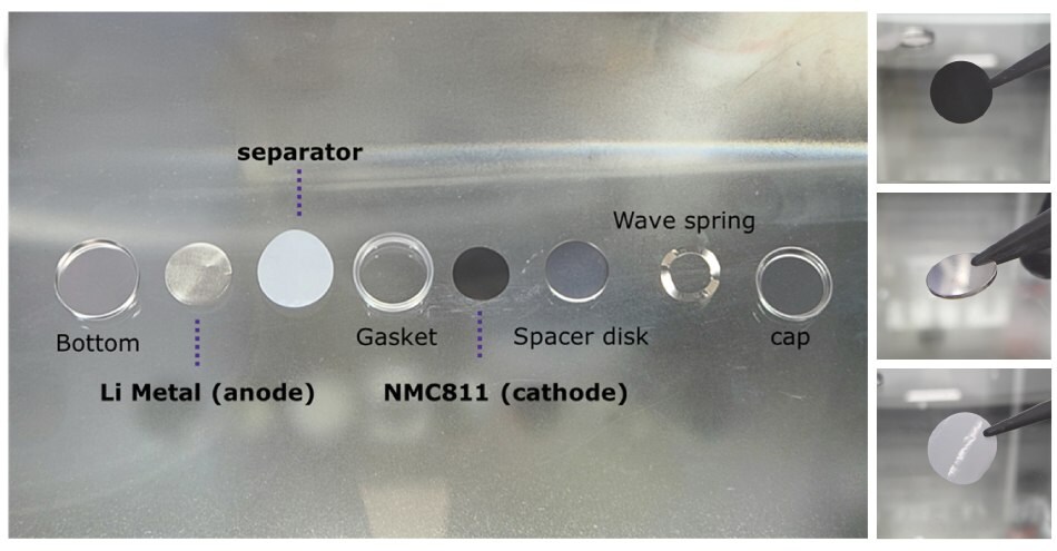
Figures 4.1 to 4.4. (4.1) Photograph of individual components used in the assembly of a 2032 coin-type battery cell, (4.2) NMC811 cathode, (4.3) Li Metal anode, and (4.4) separator.
Electrochemical Characterization
Electrochemical performance of the coated electrode was tested in the coin cell. The formation cycles consisted of one cycle at C/20, followed by two cycles at C/10.
For rate capability measurements, cells were discharged from C/5 to 5C (5 cycles each) at a fixed charge rate (C/3), then returned to C/3 for baseline cycling. Long-term cycling stability tests were carried out for up to 100 cycles at C/3 charge/discharge.
All cycling tests were performed at room temperature using a constant current-constant voltage (CC-CV) protocol, with the CV step terminated at a cutoff current of C/20. The voltage limits were set between 2.8-4.2 V vs. Li/Li+.
Results and Discussion
This section covers the electrochemical validation of the electrodes and provides guidance and tips for troubleshooting.
Electrochemical Validation
Figure 5.1 shows the specific capacity of the NMC811 electrode during long cycling at a C/3 charge–discharge rate. After 100 cycles, the electrode retained a reversible capacity of 166.31 mAh/g, corresponding to a capacity retention of 86.89%. The inset further presents the voltage profiles of charge/discharge at C/3 for selected cycles (5, 20, 40, 60, 80, and 100), allowing direct comparison of the electrode’s electrochemical response as cycling progresses. The gradual but consistent voltage evolution confirms the stability of the NMC811 cathode under repeated operation. Figure 5.2 displays the discharge capacities of the electrode at different C-rates, yielding 207.20 mAh/g at C/10, 195.95 mAh/g at C/5, 195.76 mAh/g at C/2, 195.27 mAh/g at 1C, 194.05 mAh/g at 2C, and 192.88 mAh/g at 5C.
In summary, the results obtained from the charge/discharge data, along with the capacity retention over extended cycling, demonstrate that adherence to the detailed SOP can yield high-performance batteries suitable for various applications.
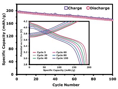
Figure 5.1. Electrochemical performance of the NMC811 cathode. Specific capacity vs. cycle number for NMC811, showing discharge performance at C/3 charge–discharge. The inset shows the voltage profiles of charge/discharge for cycles 5, 20, 40, 60, 80, and 100, providing insight into the evolution of electrochemical behavior over extended cycling.
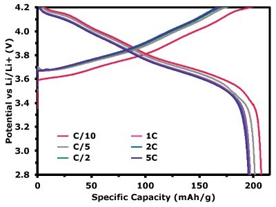
Figure 5.2. Voltage profiles of charge/discharge at different C-rates, illustrating the voltage response across various cycling conditions at C/10, C/5, C/2, 1C, 2C, and 5C.
Troubleshooting
When preparing battery electrodes, a few common problems can easily arise. One of the most frequent issues is slurry inhomogeneity, which can lead to poor coating quality and electrode cracking during drying. To minimize this, ensure that the binder and solvent are well mixed before adding the active material and conductive material, and avoid leaving large agglomerates. Another common problem is electrode detachment from the current collector. This is often caused by insufficient binder content or inadequate drying conditions. Adjusting the binder content, ensuring proper wetting of the foil, and extending drying time can help improve adhesion.
As illustrated in Figure 6, several representative failure modes can occur when the slurry composition or mixing process is not optimized. For example, cathodes prepared with an excessively high solid content (65 wt%) exhibit pronounced surface cracking after drying, which originates from internal stresses associated with solvent evaporation in a highly viscous matrix (Figure 6.1). In contrast, slurries with insufficient solid content, such as 20 wt% (Figure 6.2), tend to undergo layer separation during the coating process, while slightly higher but still suboptimal concentrations, such as 25 wt% (Figure 6.3), result in excessively thin coatings that expose regions of the current collector. Additionally, when binder content is inadequate or not well distributed, as in Figure 6.4, the dried electrode loses adhesion and delaminates from the current collector. These results emphasize the necessity of carefully balancing slurry viscosity and binder distribution to ensure uniform, adherent, and defect-free electrode coatings.
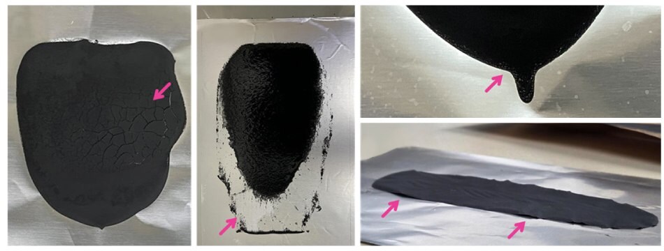
Figures 6.1 to 6.4.Representative images of electrodes fabricated under non-optimized slurry conditions, illustrating defects such as 6.1) cracking, 6.2) layer separation, 6.3) insufficient coating, and 6.4) delamination. All samples were prepared under identical coating and drying conditions, highlighting the importance of controlling slurry composition and processing parameters for reproducible, high-quality electrodes.
Another issue is poor electrochemical performance, often due to electrode loading or uneven thickness. If cells show unusually low capacity or unstable cycling, double-check the areal loading, thickness uniformity, and drying profile. Sometimes even small details, like inadequate mixing speed or incomplete dissolution of the binder, can strongly influence the result. Keeping detailed notes of parameters, such as mixing order, speed, and drying temperature helps identify and solve problems quickly.
Top 5 Tips for Achieving Better Battery Electrodes and Cell Assembly
- Mix order matters: The binder should be completely dissolved in the solvent before adding the active material and conductive additive. At this stage, ensure good dispersion of the conductive carbon, as proper distribution is essential to form continuous electron pathways throughout the electrode. Poor dispersion or agglomeration can lead to reduced conductivity and degraded cycling performance.
- Control viscosity: Aim for a slurry that spreads smoothly on the current collector without being overly runny. This SOP was prepared with a solid content of 35 wt%, which provides an ideal viscosity and can be used as a reference point when adjusting compositions.
- Uniform coating is key: Use consistent casting speed and doctor blade height to ensure homogeneous thickness and surface uniformity.
- Dry at controlled temperature: Dry electrodes at 80°C to ensure steady solvent removal and uniform drying, leading to better film adhesion. Users may adjust the drying profile depending on the thickness of their electrodes, but 80°C provides a robust starting point.
- Control electrolyte injection during cell assembly: Add the electrolyte slowly and in the recommended volume to ensure uniform wetting of the separator and electrodes. Over- or under-filling can cause poor electrochemical performance and lead to inconsistent test results.
Conclusion
In conclusion, this guide serves as a vital resource for researchers involved in the fabrication of cathode electrodes using NMC811. By adhering to the outlined procedures, users can ensure the production of high-quality electrodes that meet the demands of modern battery applications. The meticulous attention to material preparation, environmental controls, and safety measures highlighted throughout this document is crucial for optimizing performance and reliability in battery technology. As the demand for efficient energy storage solutions continues to grow, advancements in cathode fabrication techniques will play a pivotal role in driving innovation in the field.
Related Products
References
To continue reading please sign in or create an account.
Don't Have An Account?